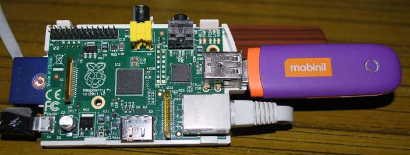
Reading and writing from GPIO ports from Python
http://raspberry.io/projects/view/reading-and-writing-from-gpio-ports-from-python/
Reading and writing from GPIO ports from Python

This tutorial covers the setup software and hardware to read and write the GPIO pins on a Raspberry Pi running the latest Raspbian operating system.
We will showing how to read from a physical push-button from Python code, and control an LED.
Related categories: Tutorial
Step 1: Install Python development tools
Open a terminal on the Raspberry Pi either via the desktop or by SSH’ing in (default credentials are pi/raspberry).
Run the following commands to install some basic Python development tools:
sudo apt-get update
sudo apt-get install python-dev python-pip
sudo pip install --upgrade distribute
sudo pip install ipython
Step 2: Install GPIO library
While the default Raspbian image does include the RPi.GPIO library, we would like to install a newer version to get access to a newer API for callbacks.
sudo pip install --upgrade RPi.GPIO
As of this writing the current version of 0.5.0a but you may see a more recent version later.
Step 3: Connect the button
For the first part of this we will be using a single push button. Normally the top two pins and bottom two pins are not connected, but when pressing the button a connection is formed, allowing current to flow. We will put a 330 Ohm resistor in-line with the switch to protect the GPIO ping from recieving too much current.
I have used GPIO4 for this example, but any GPIO pin not otherwise in use will work fine, just update the pin number in later code samples.
Important: Never connect GPIO pins to the 5V power supply
The two 5V supply pins on the breakout board are very useful for powering complex chips and sensors, but you must take care to never accidentally use them to directly interface with the GPIO pins. The GPIO system is only designed to handle 3.3V signals and anything higher will most likely damage your Raspberry Pi.
Step 4: Read the button from Python
Remember that you must run your interpreter as root (ex. sudo ipython).
First we need to configure the GPIO pins so that the Raspberry Pi knows that they are inputs:
import RPi.GPIO as GPIO
GPIO.setmode(GPIO.BCM)
GPIO.setup(4, GPIO.IN, pull_up_down=GPIO.PUD_DOWN)
The pull_up_down argument controls the state of the internal pull-up/down resistors. Looking back at the circuit diagram above you can see that when the button is not pushed, the GPIO pin is effecitvely not connected to anything. This is referred to as “floating”, and it means that the voltage there can be unpredictable. A pull-down adds an additional resistor between the pin and ground, or put simply forces the voltage when the button is not pressed to be 0.
With the pin configured we can now do a simple read of the button:
print GPIO.input(4)
This should output False if the button is released and True if the button is pressed. Try it a few times each way to make sure you wiring and configuration is correct.
Step 5: Setup callbacks
While directly checking the state of the button is nice, often we want to take action at the moment the button is pressed. To do this we will use the edge edection mode of our RPi.GPIO library:
GPIO.add_event_detect(4, GPIO.RISING)
def my_callback():
    print 'PUSHED!'
GPIO.add_event_callback(4, my_callback)
Internally this starts a background thread that watches for state transitions, in this case we have specifically asked to only be notified of transitions from False to True (or more specifically, from 0 to 3.3V on the pin). While the use of this background thread is suffcient for most simple applications, complex asynchronous applications may want to use something like Twisted.
As you press and release button you may see some instances where PUSHED! is printed more than once during a single press, or possible printed while you are releasing the button. This is because our simple circuit is very “noisy” in the moments during a press or release. This kind of multiple-triggering is referred to as “bounce” and the process of removing it is “debouncing” the input. Several strategies exist to debounce inputs ranging from simple software solution to complex hardware augmentations. For the purposes of the rest of this guide we will ignore this artifact, however as you build more complex things you will most likely want to look into debouncing solutions.
Step 6: Controlling an LED
Look at the diagram above to connect an LED and another 330 Ohm resistor to another GPIO pin. As before we use the resistor to limit the current through the GPIO pin, thus protecting the Raspberry Pi from dangerous over-draw. Unlike other components we have used before, LEDs only work when power is flowing in the correct direction, so make sure the flatter side of the LED is connected to the resistor (or more importantly, that the flatter edge must be towards the direction connected to ground).
Once you have the LED connected, we can control it from Python:
GPIO.setup(25, GPIO.OUT, initial=GPIO.LOW)
GPIO.output(25, GPIO.HIGH)
This should light up the LED.
Step 7: Combining it all
Now we have both an input and output that we can control from Python, so lets wrap it all up:
import RPi.GPIO as GPIO
GPIO.setmode(GPIO.BCM)
GPIO.setup(4, GPIO.IN, pull_up_down=GPIO.PUD_DOWN)
GPIO.setup(25, GPIO.OUT, initial=GPIO.LOW)
GPIO.add_event_detect(4, GPIO.BOTH)
def my_callback():
    GPIO.output(25, GPIO.input(4))
GPIO.add_event_callback(4, my_callback)
Now when you press the button, the LED will turn on. A simple application but the same technique can be easily applied to anything from a REST API to the lights in your home!
Comments


